
DAVID BEHAR
Rétro-conception de pièces automobiles pour une Matra jet 5S
.png)
Ayant une grande attirance pour l'automobile et voulant développer mes compétences dans ce domaine, j'ai choisi ce projet en fin de première année de BUT. Je n'avais jamais entendu parler de la rétro-conception auparavant, le fait de reconcevoir et de fabriquer des pièces d'une ancienne voiture de course m'attirait beaucoup. Je souhaitais pouvoir apporter ma pierre à l'édifice, afin de rendre la voiture la plus performante possible.
J'ai travaillé sur ce projet pour une durée de 2 semestres à l'IUT avec une équipe composée de 3 personnes encadrées par un tuteur de projet.
.png)
Présentation du projet
Le projet avait pour objectif de rétro-concevoir et fabriquer diverses pièces automobiles destinées à une Matra-Sports Djet 5S. La rétro-conception est un processus qui consiste à reproduire une pièce à partir d'un modèle existant souvent en ayant peu d’informations sur les plans ou les dessins d'origine. Elle est souvent utilisée dans la restauration de voitures anciennes lorsque les pièces de rechange ne sont plus disponibles sur le marché. La réalisation de ces pièces nécessite l'utilisation de différentes technologies telles que la CAO, l'usinage sur MOCN*, l'impression 3D, la découpe laser et la fabrication additive. Ces technologies permettent de produire des pièces précises et résistantes qui répondent aux normes de qualité requises pour l'industrie automobile.
Plusieurs techniques de rétro-coneption peuvent être utilisées seules ou en combinaison pour créer un modèle numérique en 3D d'une pièce existante et permettre ainsi la fabrication ou la modification de cette pièce. Dans ce projet, la rétro-conception a permis de reproduire des pièces qui ne sont plus produites pour la Matra-Sports Djet 5S, nous avons ainsi pu restaurer ces pièces tout en les améliorant. Pour notre part, nous avons utilisé un seul mode de production, l’usinage sur MOCN en fraisage et tournage. En plus de l'aspect technique, ce projet présente également un intérêt historique et culturel. En effet, la Matra-Sports Djet 5S est un modèle de voiture sportive française qui a été produit dans les années 1960. Nous avons pu apporter notre pierre à l’édifice.

Visite chez le client pour voir l'implantation des différentes pièces commandées et comprendre leurs fonctionnements.


Platine de vitesse
cylindre de platine de vitesse
Début septembre 2022, nous avons eu notre première séance de projet, où nous avons rencontré notre client. Après avoir fait connaissance avec lui, il nous a donné notre première commande un cylindre de platine de vitesse avec un cahier des charges. La pièce permet de maintenir un soufflet en caoutchouc du levier de vitesse et de guider des pièces en rotation permettant la rotation d'une tige en contact à l'autre extrémité avec la boite de vitesse de sa voiture une Matra Jet 5S.
Cette pièce avait déjà été usinée par des élèves de l'année dernière, mais il manquait un perçage, un taraudage et le chanfreinage de la pièce pour la rendre légèrement cylindrique. J'ai décidé de m'orienter sur la partie fabrication, pour ce faire, j'ai rédigé la gamme de fabrication et aidé a réaliser la FAO de cette pièce.

Cylindre
Platine
Ancien ensemble d'origine cassé

Cylindre de vitesse CAO

Dessin coté fournit par le client

Cylindre de vitesse usiné

Taraudage
Perçage débouchant
Chanfreinage
Ensemble déjà usiné

Éclaté platine de vitesse
Porte-moyeu
Notre deuxième commande a été la fabrication de portes-moyeu. Ils permettent de supporter la roue pour faciliter son braquage. Ils accueillent en leurs centres des roulements à chaque extrémité, calés entre eux, à travers desquels passent les fusées. Après une phase d'analyse du cahier des charges puis de démontage du porte moyeu, nous avons scanné la pièce grâce à un scanner 3D.
Nous avons ensuite effectué les mesures de la pièce grâce à une MMT (machine à mesurer tridimensionnelle), ce qui nous a permis de modéliser la pièce en 3D. En cherchant des bruts sur Internet, nous nous sommes rendu compte avec le client que le prix de revient de la pièce serait cher, il a donc décidé d'annuler cette commande. Il nous a finalement demandé de réusiner les deux porte- moyeux d'origine, afin de réadapter le système de guidage. Il a donc fallu appliquer quelques modifications au système de base : usinage de l'alésage déjà présent, modification de l'entretoise et du type de roulement (un seul roulement conique à double rangé de billes au lieu de 2 avant). Je me suis occupé de concevoir la bague de roulement.

Éclaté Transmission

Éclaté porte moyeu
Le porte moyeu (5211) est une pièce que l’on retrouve en deux exemplaires sur le véhicule. Chacun est placé de part et d’autre au niveau des roues à l’arrière. Son rôle est d’effectuer la liaison entre le train arrière de la voiture et l’ensemble du système autour de la roue. En se référant à la vue éclatée ci-dessous, on retrouve dans le système, son axe communément appelé la fusée (5207), des entretoises (5210) logées dans le porte moyeu. Les différents composants tels que les roulements (5207, 5208) sont ceux qui guident le mouvement de rotation entre le porte moyeu et la fusée. Tout cela assurant le mouvement de rotation de la roue par l'intermédiaire de la fusée. Le tout relié au disque de frein (5203) ou la roue viendra se fixer.
Une fois l’étape du démontage achevée, nous avions besoin de mesurer le porte moyeu afin de récupérer toutes ses dimensions. Dans un premier temps, afin d’effectuer des mesures sur des surfaces propres, nous avons donné un coup de neuf à la pièce en la passant à la sableuse de l’atelier.
Après cela, nous avons pu passer au scan de la pièce :


Scan de la pièce

Pièce en cours de scan

Mesure sur MMT
Un scanner 3D, est un dispositif qui permet de numériser un objet réel en trois dimensions pour créer un modèle numérique 3D. Voici comment fonctionne un scanner de rétro-conception :
-
Acquisition de données : Le scanner émet une lumière structurée sur l'objet, qui est ensuite reflétée et captée par les caméras du scanner. Les données acquises sont ensuite stockées sous forme de nuage de points.
-
Traitement des données : Les données brutes acquises par le scanner doivent être traitées pour éliminer le bruit et les erreurs de mesure. Cela peut être effectué à l'aide d'un logiciel spécialisé qui utilise des algorithmes de traitement d'images et de nuages de points pour produire un modèle 3D précis.
-
Modélisation 3D : Les données traitées sont utilisées pour créer un modèle numérique 3D de l'objet. Ce modèle peut être visualisé, modifié, exporté vers d'autres logiciels de CAO/FAO, ou utilisé pour la fabrication d'une réplique de l'objet.
On déplace la pièce sous différents angles et on scanne à chaque fois jusqu’à obtenir toute la surface. Une fois le premier plan complet, on retourne la pièce et on effectue cette fois encore les scans. On effectue les scans des deux plans dans deux séries différentes que l’on fusionne par la suite pour obtenir le modèle complet.

Bague de roulement
La bague de roulement d'un porte moyeu est une pièce essentielle qui sert à soutenir la charge axiale et radiale de la roue et à maintenir sa position dans le porte moyeu. Elle permet à la roue de tourner librement tout en étant maintenue en place de manière stable.
La bague de roulement peut être montée directement sur le porte moyeu ou être intégrée dans le roulement de la roue elle-même. Elle est souvent en acier trempé pour résister aux charges élevées et aux contraintes thermiques associées aux mouvements et aux frottements.
Détermination du matériau utilisé
Pour connaître le matériau utilisé pour la bague de roulement d’origine, j'ai réalisé des essais de dureté Vickers.
J'ai ainsi déterminé que l’acier utilisé devait sûrement être un acier allié 52100 (100C6). Également connu sous le nom d'acier à roulements, il est souvent utilisé pour les roulements à billes et les bagues de roulement en raison de sa haute résistance à la fatigue et à l'usure.
Par manque de temps, j'ai décidé de prendre de l’acier XC38 (C35) disponible à l’atelier. J'ai également réalisé des essais de dureté Vickers sur ce brut préalablement poncé pour s’assurer de sa bonne résistance.

Grâce à ces essais, j'ai constater que l’acier XC38 était quasiment deux fois supérieur au précédent. Au niveau de la masse volumique, l’acier 100C6 est d'environ 7840 kg/m3 et celle de l’acier XC38 est de 7850 kg/m3. Nous avons une petite différence, ce qui est bénéfique.


CAO
Pour ce qui est de la partie conception de la bague de roulement, j'ai pris les valeurs de la bague du deuxième porte moyeu déjà existante et j'ai fait en sorte que la position indexée du roulement dans le porte moyeu soit exactement la même. Pour cela, j'ai relevé les valeurs de l’épaulement du fond de la bague où le roulement prendra appui et l’épaisseur de la bague.


Gamme de fabrication

Contrats de phase


FAO

Pièce usinée après la phase 10

Vérification de la phase 10

Pièce usinée après la phase 20
Je n'ai malheureusement pas eu le temps, d’usiner la bague de roulement, mais ceux qui continueront le projet pourront le faire très facilement, car les contrats de phase sont faits et la FAO aussi. Ils devront juste choisir les outils disponibles à l’atelier.
Mors doux
J'ai dû usiner des mors doux, afin de pouvoir usiner la phase 20 de la bague de roulement. Les mors doux s'adaptent parfaitement à la forme de la pièce à maintenir, pour ne pas la déformer ou la marquer. De plus, ils offrent une surface de maintien plus large que les mors durs, ce qui permet une meilleure répartition des forces de serrage et donc une meilleure stabilité de la pièce lors de l'usinage. Il a tout d’abord fallu trouver des mors doux s’adaptant sur le TCN 4 de l’atelier, car il était le moins occupé.
Après avoir trouvé des mors aux dimensions adaptées, j'ai généré le programme sur la machine grâce à un cycle de cylindrage intérieur. Pour le serrage des mors, j'ai eu besoin d’une étoile qui n’était pas disponible à l'atelier. Pour la remplacer, j'ai scié une bague qui permet de les contraindre et de les serrer autour de quelque chose, pour obtenir un diamètre à usiner.

Mors doux
Bague de serrage
Alésomètre
Les mors serré, j'ai pu mesurer à l'alésomètre, la dimension en X qui correspond au diamètre de l’alésage des mors étant déjà légèrement usiné. Pour la dimension en Z, je l'ai déterminé en mesurant la longueur totale et en soustrayant une épaisseur permettant de faire une liaison appui plan fiable. Les conditions de coupe ont été déterminées en fonction des mors qui sont en acier doux.

Programme cycle de cylindrage intérieur
Pour le diamètre usiné, j'ai mis 58 mm, pour contrôler l’écart entre le diamètre voulu et le diamètre usiné. Il manquait 0.08 mm, j'ai donc rajouté cette dimension au diamètre que l’on voulait vraiment (60.088 mm). Suite à l'opération d'usinage par contournage intérieur avec l’outil de contournage intérieur, j'ai constaté que la longueur importante de l'outil créait du porte-à-faux qui a généré des vibrations et altéré l'état de surface de la pièce. Suite à cela, j'ai scié un outil plus robuste, afin de lui donner une longueur facilitant l’usinage.

Outil de contournage intérieur

Outil de contournage intérieur scié
Pour finir, j'ai inscrit le nouveau diamètre des mors usinés et le nouveau diamètre que je souhaité. Après plusieurs essais, je suis arrivé au diamètre souhaité.

Programme cycle de cylindrage intérieur

Mesure des mors à l'aide de l'alésomètre
Après l’usinage, j'ai obtenu des mors doux avec un bon état de surface, me permettant d’usiner la phase 20 de la bague de roulement.
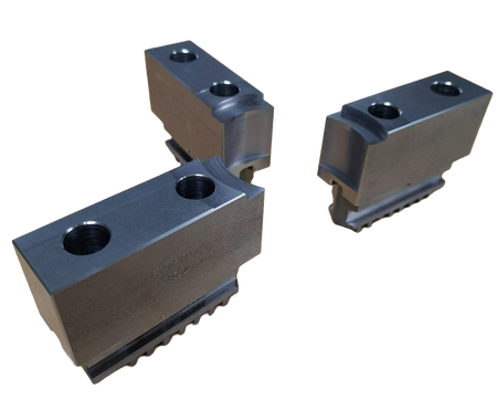
Mors doux fini au Ø60.088 mm
Doigt de renvoi
J'ai décidé de m'occuper de la troisième commande du client, un doigt de renvoi. La Matra Djet 5S est équipée d'une platine de vitesse pour changer les vitesses manuellement. Le doigt de renvoi est un élément mécanique situé à l’intérieur de la platine de vitesse, il est utilisé dans le système de transmission de la voiture.
Lorsque le conducteur actionne le levier de vitesses, le doigt est mis en mouvement. Une rotule vissée dans le trou taraudé du doigt le fait rotuler et un axe monté sur le doigt de renvoi à l’aide d’une goupille passant par la boite de vitesse lui permet de transmettre un mouvement latéral. Cela permet de transmettre le mouvement à la fourchette de sélection des vitesses.
La fourchette de sélection est un mécanisme qui coulisse latéralement sur un axe pour engager les différents pignons de la boîte de vitesses en fonction de la vitesse sélectionnée. Lorsque le doigt de renvoi est en position, il permet de verrouiller le mécanisme de changement de vitesse dans la position sélectionnée. Cela permet au conducteur de maintenir la vitesse souhaitée tout en accélérant ou en ralentissant la voiture.
Il n'y avait pas vraiment de cahier des charges pour cette pièce, mais juste un dessin coté et des informations transmises oralement par le client, il souhaitait une série d'environ 5 pièces.
Éclaté platine de vitesse
CAO
Le doigt de renvoi est conçu pour résister à des charges élevées et pour avoir une grande résistance à l'usure, car il est soumis à des contraintes importantes chaque fois que le conducteur change de vitesse.
Après une étude approfondie, j'ai étudié les différentes sollicitations auxquelles le doigt de renvoi était soumis. Le doigt de renvoi d’origine était en acier C35 (XC38), afin d'alléger le doigt de renvoi et pour des raisons de facilités d’usinage, j'ai choisi de faire cette pièce en Alu 2017.
Pour obtenir un dimensionnement optimisé et respectant les caractéristiques de résistance mécanique du doigt de renvoi d’origine, il a fallu modifier la pièce d’origine.


Reproduction du dessin coté en CAO avec un ajout de congés pour diminuer l'encombrement de la pièce.
Il y avait une contrainte au niveau de l’usinage de la pièce. Il n’était pas possible de réaliser la pièce de manière conventionnelle sur une fraiseuse 3 axes (Diam 300), car les outils auraient touché les mors de l'étau pendant l’usinage. Pour pallier cela, il a fallu réaliser un usinage étalon aussi appelé usinage en semelle permettant de ne pas être contraint de prendre un brut avec une hauteur plus grande. Cet usinage consiste à effectuer les différentes opérations d’usinage et à ensuite usiner la surépaisseur entre les cales et le dessous de la pièce finie. On retourne la pièce, on fait un surfaçage et notre pièce est finie. Il a donc fallu adapter les dimensions du brut et surtout vérifier sa disponibilité au magasin de l’IUT pour ne pas être contraint lors de l’usinage. Dans la gamme d’usinage, j'ai choisi d’effectuer les opérations d’usinage suivantes.
Gamme de fabrication

Contrats de phase


Outils utilisés pour la fabrication du doigt de renvoi

Fraise 2 tailles, plaquettes carbures Ø16
Foret hélicoïdale Ø12
Fraise 2 tailles, acier rapide
Foret à pointer Ø16
Taraud M12
Foret Ø10,15

Phase 10
FAO de la pièce
Choix des :
-
Opérations d'usinage
-
Outils
-
Conditions de coupes

Phase 20
Usinage sur une fraiseuse 3 axes (Diam 300)
-
Mesure des jauges outils
-
Calculs des DEC
-
Montage des outils
-
Insertion du programme dans la machine
-
Usinage à vide
-
Mise en butée du brut
-
Usinage de la pièce

Mise en position - Phase 10

Mise en position - Phase 20

Usinage - Phase 10
Usinage - Phase 20
Pièce finie
-
Mesure de la pièce pour contrôler si les dimensions respectent l'intervalle de tolérance.
-
Correction des jauges outils.
-
Usiner la pièce en appliquant les corrections de jauges outils.
-
Réitérer les étapes précédentes jusqu'à l'obtention des dimensions voulues.


L'analyse approfondie de la Matra Djet 5S dans le cadre de ce projet m'a non seulement fait découvrir des procédés d'usinage essentiels (étalon, montage modulaire), mais m'a surtout permis de saisir avec rigueur la fonction et les caractéristiques critiques (géométrie, choix des matériaux) des différentes pièces automobiles. Cette démarche a consolidé ma compréhension de leur impact direct sur la performance et la conception globale du véhicule.